Properly wiring an automatic water tank level switch is critical for ensuring reliable liquid level monitoring and control. Whether you’re managing industrial reservoirs, commercial water systems, or agricultural storage tanks, a well-installed float switch safeguards against overflows, dry runs, and equipment damage. This guide walks you through the process of connecting an Automatic Plastic Water Tank Level Switch – IP67 Electric Liquid Float Sensor to your control panel, emphasizing safety, efficiency, and compliance.
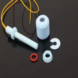
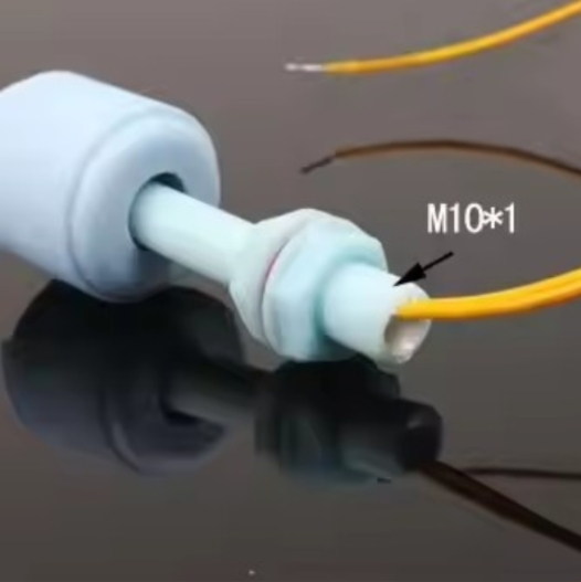
The Automatic Plastic Water Tank Level Switch – IP67 Electric Liquid Float Sensor is designed for precision and durability. Key features include:
– IP67 waterproof housing for resistance to dust, moisture, and harsh environments.
– Magnetic reed switch with NO/NC (normally open/normally closed) contacts for flexible signal output.
– PP material construction and vertical mounting, compatible with temperatures from -10°C to +85°C.
– CE/ROHS/REACH certifications, ensuring compliance with international safety standards.
This sensor is ideal for integration with pumps, alarms, and automation systems, providing real-time liquid level data to your control panel.
Step 1: Pre-Installation Preparation
Tools Required:
– Screwdrivers (flathead and Phillips).
– Wire strippers and crimping tools.
– Multimeter for continuity testing.
– UL-listed electrical cables (rated for 200VDC/1.5A).
Safety First:
– Disconnect power to the control panel and pump system.
– Verify that the tank is empty or at a safe level for installation.
Step 2: Mounting the Float Sensor
1. Positioning:
– Attach the sensor vertically to the tank wall using mounting brackets. Ensure the float moves freely without obstructions.
– For multi-level control, install additional sensors at different heights.
2. Sealing:
– Tighten the IP67-rated gland nut to secure the cable entry point, preventing water ingress.
Step 3: Wiring the Sensor to the Control Panel
1. Identify Contacts:
– Locate the NO (normally open) and NC (normally closed) terminals on the sensor.
– For pump control, NO contacts trigger activation when the liquid rises; NC contacts signal low-level alerts.
2. Connect Wires:
– Strip 6-8mm of insulation from the sensor’s cables.
– Link the NO/NC wires to the control panel’s input terminals (refer to your panel’s manual for specific terminals).
– Ground the sensor’s earth wire to the panel’s grounding point.
3. Secure Connections:
– Use crimp connectors or terminal blocks to prevent loose wires.
– Apply dielectric grease to exposed metal parts to reduce corrosion.
Step 4: Testing and Calibration
1. Power On:
– Reconnect the control panel’s power supply.
– Simulate liquid levels by manually lifting or lowering the float.
2. Verify Signals:
– Use a multimeter to confirm that the NO/NC contacts open/close as expected.
– Check the control panel’s display or indicator lights for proper response.
3. Adjust Sensitivity:
– If your system supports it, fine-tune alarm or pump activation thresholds via the panel’s software.
Step 5: Maintenance and Troubleshooting
– Monthly Checks: Inspect cables for wear, corrosion, or rodent damage. Clean the float of debris.
– Annual Calibration: Re-test continuity and signal accuracy.
– Common Issues:
– False signals: Ensure the float isn’t stuck and the magnetic reed switch is intact.
– No power: Verify connections and replace damaged cables.
Why Choose the Automatic Plastic Water Tank Level Switch?
The Automatic Plastic Water Tank Level Switch – IP67 Electric Liquid Float Sensor simplifies liquid management with its rugged design and plug-and-play compatibility. Its magnetic reed switch ensures precise, drift-free signaling, while the IP67 rating guarantees reliability in demanding environments.
Optimize Your Liquid Control System Today
For seamless integration of automatic water tank level switches into your operations, trust a sensor built for accuracy and longevity. Visit our website to explore technical specifications, compliance details, and bulk pricing options—or contact our engineering team for personalized wiring diagrams and installation support.
Comments are closed