 Explore the critical role of IP67-rated, 10A metal push button switches in marine control systems. This technical deep dive covers material science, electrical performance, and real-world maritime applications with wiring examples. Ensure reliability where failure is not an option.
1. Introduction: The High-Stakes World of Marine Control
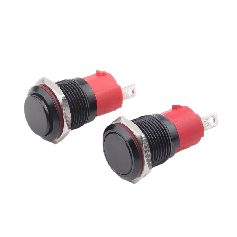
In the unforgiving environment of the open sea, every component on a vessel is subject to a relentless test of durability. Control panels, the nerve center of ship operations, are particularly vulnerable. A single switch failure in a critical system—be it bilge pumping, navigation lighting, or emergency ventilation—can cascade from an inconvenience to a severe safety incident. This article focuses on a foundational yet often underestimated component: the manual push button switch. We will examine why a 16mm IP67 Waterproof Metal Push Button Switch, rated for 10A loads, is not merely a part but a critical safety and reliability investment for marine and offshore applications.
2. Deconstructing the Threat: Environmental & Operational Challenges
Marine switches face a unique confluence of destructive forces:
Salt Spray & Corrosion: Chloride ions accelerate metallic oxidation, leading to contact failure and housing degradation.
Constant Vibration & Shock: Engine harmonics and wave impacts can loosen connections and damage internal components.
Humidity & Water Ingress: Condensation and direct spray can cause short circuits, insulation breakdown, and contact corrosion.
UV Exposure & Temperature Extremes: Sunlight degrades plastics, while temperature swings from polar cold to engine room heat test material stability.
Frequent, High-Load Cycling: Systems like winches or pumps require switches capable of handling inrush currents and inductive load switching.
3. Engineering the Solution: A Technical Analysis of a Marine-Grade Switch
Using the specified 16mm metal push button as a case study, let’s translate its technical parameters into engineering benefits.
A. The Seal: IP67 Protection as a Non-Negotiable Standard
What IP67 Means: “6” indicates complete protection from dust. “7” certifies the switch can withstand immersion in 1 meter of water for 30 minutes at the button face. For marine panels, this is the minimum standard.
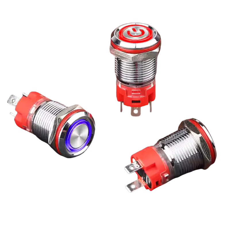
Implementation: Achieved through a combination of a laser-welded or ultrasonically sealed metal housing, an ethylene propylene diene monomer (EPDM) or silicone waterproof ring, and a precision-machined interface between the button (SUS316) and the bushing.
B. The Structure: Materials Engineered for the Sea
| Component | Material (Example) | Why It Matters for Marine Use |
|---|---|---|
| Housing | SUS304 Stainless Steel / Brass Nickel-Plated | SUS304 offers excellent general corrosion resistance. Brass with electroless nickel plating provides superior protection against saltwater pitting and offers a conductive path for grounding. |
| Button/Actuator | PC (Polycarbonate) & SUS316 Stem | PC is impact-resistant. SUS316 (“Marine Grade” stainless) contains molybdenum for exceptional resistance to chloride-induced pitting and crevice corrosion. |
| Contacts | Silver Tin Oxide (AgSnO₂) Alloy | Superior to pure silver for DC and inductive loads. Resists material transfer and welding during arc interruption, crucial for the 10A/24V DC rating with motors. |
| Base | Modified PA66 (Nylon) | Flame-retardant (UL94 V-0), resistant to fuels, oils, and hydrolysis (moisture absorption), preventing deformation. |
C. The Electrical Heart: Performance Under Load
Rating Decoded: The switch is dual-rated.
DC-13: 12V/24V, 10A: This is for DC loads like solenoids, relays, and most importantly, DC motors (pumps, actuators). The 10A rating must handle the motor’s locked-rotor inrush current.
AC-15: 110V/250V, 15A: For AC lighting circuits, heaters, or general power distribution onboard.
Contact Resistance: ≤50mΩ ensures minimal voltage drop and heat generation, vital for maintaining system voltage in long cable runs common on ships.
Lifecycle: >30,000 electrical cycles at full load and >1,000,000 mechanical cycles ensure decades of service, reducing lifecycle cost.
4. From Specification to Application: Real-World Wiring Scenarios
Scenario 1: Bilge Pump Manual Override Control
Function: A maintained (latching) switch provides a manual “ON” override for an automatic bilge pump system.
Why This Switch? IP67 prevents failure from splashing or condensation in the bilge. The 10A DC rating handles the pump motor’s inductive load. Silver tin oxide contacts resist arcing.
Wiring Concept: The switch is placed in series with the pump motor’s positive leg, after the automatic float switch. A red, 24V LED version provides clear “PUMP ACTIVATED” visual status.
Scenario 2: Navigation & Anchor Light Selector Panel
Function: A bank of momentary (self-resetting) switches allows the crew to select “Running Lights,” “Anchor Light,” or “All Off.”
Why This Switch? The compact 16mm size allows multiple switches in a dense panel. The brass nickel-plated housing resists tarnishing in the exposed bridge environment. Different LED colors (White for Running, Red for Anchor) prevent selection errors.
Wiring Concept: Each switch’s output goes to a dedicated relay coil. The relay’s contacts then handle the higher current for the actual light circuits. This uses the switch for low-current control only, extending its life.
Scenario 3: Engine Room Emergency Stop (E-Stop)
Function: A large, red, illuminated momentary switch to cut power to non-essential equipment in an emergency.
Why This Switch? While not a certified emergency stop device (which requires positive-guided contacts per ISO 13850), it can be used for auxiliary systems. The high-brightness LED and metal construction provide clear visibility and durability in the harsh engine room.
Wiring Concept: The switch is wired as a normally closed (NC) circuit in the control loop of multiple motor starters or a master relay. Pressing it breaks the circuit, stopping the equipment. The LED is wired to illuminate when the circuit is powered (system normal), providing a “system live” indication.
5. Integration Best Practices for Panel Builders
Panel Cutout: Use the precise 16~16.1mm hole specification. A clean, deburred hole is essential for the sealing ring to compress evenly.
Wiring: Use fully insulated female quick-connect terminals matching the 4.8×0.8mm pin size. Crimp them properly—vibration is the enemy of loose connections.
Grounding: If using a metal panel, ensure the switch’s metal housing makes good contact with the grounded panel for EMI shielding and safety.
6. Conclusion: Specifying for Total Cost of Ownership
Choosing the right switch is an exercise in risk mitigation and total cost calculation. The marginally higher upfront cost of a true marine-grade component like this IP67 metal push button is dwarfed by the costs associated with:
Unscheduled downtime for repair.
Emergency parts delivery to a remote port.
A potential safety incident caused by control failure.
By specifying switches based on material compatibility, environmental protection, and electrical performance—not just price and appearance— engineers and shipbuilders create control systems that are as resilient as the vessels they operate.
Ready to specify reliability? Download our detailed 3D models, wiring schematics, and full material compliance sheets for this switch series to integrate into your next marine panel design.

Comments are closed