
Pushbutton switches are critical components in motor control systems, enabling safe and precise operation of AC/DC motors across industrial applications. This guide explores their wiring principles, operational logic, and PLC integration, with a focus on three-phase motor control.
1. Core Components of a Motor Control Circuit
A basic three-phase AC motor control circuit typically includes:
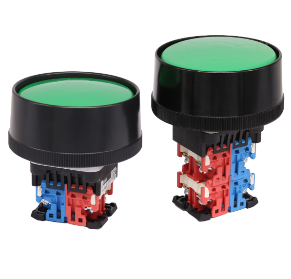
- Momentary Pushbuttons: Normally Open (NO) “Start” and Normally Closed (NC) “Stop” buttons.
- Motor Starter Coil (M): Energizes to close main contacts and start the motor.
- Overload Relay (OL) Contacts: Normally closed, cutting power if motor overheats.
- Sealing Contacts (M Auxiliary Contacts): Maintain circuit continuity after the “Start” button is released2.
2. Wiring Logic: Start/Stop Control
Wiring Diagram Overview
- The Start button (NO) is wired in series with the motor starter coil (M), while the Stop button (NC) and OL contacts are also in series.
- When the Start button is pressed, current flows through the circuit, energizing the M coil. This closes the main contacts (starting the motor) and the auxiliary M contacts (sealing the circuit).
- Releasing the Start button keeps the circuit active via the auxiliary M contacts. Pressing Stop (NC opens) or tripping OL (NC opens) de-energizes M, stopping the motor2.
Key Feature: Momentary action ensures the motor only runs when intended, preventing unintended continuous operation.
3. PLC-Based Motor Control
Modern systems often replace hardwired circuits with Programmable Logic Controllers (PLCs) for flexibility.
Ladder Logic Programming
- Inputs: NO Start (I0.0) and NC Stop (I0.1) buttons are connected to PLC input modules.
- Output: Motor starter coil (Q0.0) is controlled by ladder logic. A “sealing contact” (Q0.0 NO) is programmed to maintain the circuit after Start is released2.
Advantages Over Hardwiring
- Flexibility: Easily reconfigure logic without rewiring.
- Diagnostics: Monitor button status and faults via PLC software.
- Scalability: Integrate with sensors (e.g., limit switches) for automated control sequences.
4. Types of Pushbuttons for Motor Control
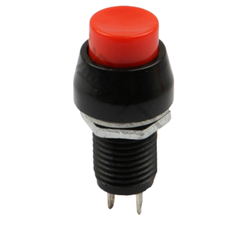
- Momentary (Non-Locking): Automatically reset when released (ideal for Start/Stop).
- Normally Open (NO): Closes circuit when pressed (Start function).
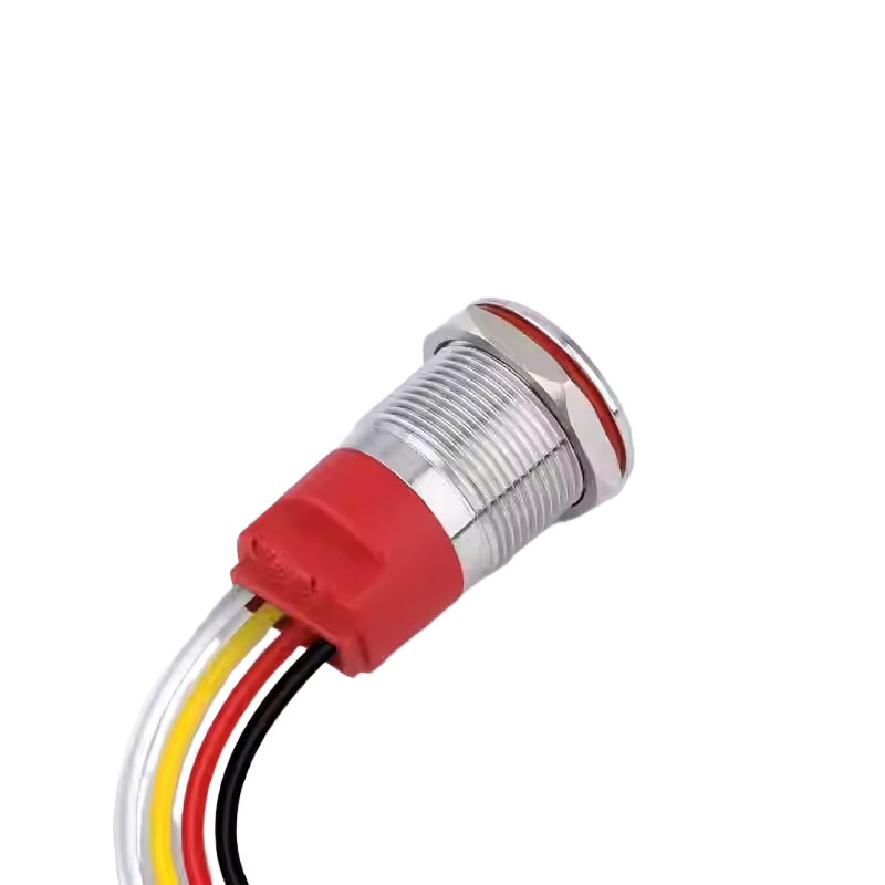
- Normally Closed (NC): Opens circuit when pressed (Stop/emergency stop function)34.
Safety Note: Emergency stop buttons use NC contacts to ensure circuit interruption even if the button fails.
5. Troubleshooting Common Issues
- Motor Fails to Start: Check for open Start button, faulty OL contacts, or PLC input errors.
- Motor Won’t Stop: Verify Stop button NC contacts are not welded closed; inspect PLC output logic.
- Intermittent Operation: Clean button contacts or replace worn switches to eliminate arcing.
6. Application Examples
- Conveyor Systems: Start/Stop buttons for line control.
- Pumps: Momentary switches for priming or manual override.
- Industrial Machinery: Emergency stop circuits with redundant NC buttons.
Conclusion
Pushbutton switches are the “human-machine interface” of motor control, bridging operator intent and mechanical action. Whether in traditional hardwired setups or PLC-based systems, understanding their wiring and logic ensures safe, reliable motor operation.
Stay tuned for our next guide on advanced PLC ladder logic for motor reversing circuits!